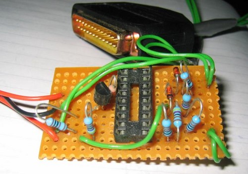
Thesis/Project on Vehicle Monitoring and Security System

In this modern, fast moving and insecure world, it is become a basic necessity to be aware of one’s safety. Maximum risks occur in situations wherein an employee travels for money transactions. Also the Company to which he belongs should be aware if there is some problem. What if the person traveling can be tracked and also secured in the case of an emergency?! Fantastic, isn’t it? Of course it is and here’s a system that functions as a tracking and a security system. It’s the VMSS. This system can deal with both pace and security.

The VMSS (Vehicle Monitoring and Security System) is a GPS based vehicle tracking system that is used for security applications as well. The project uses two main underlying concepts. These are GPS (Global Positioning System) and GSM (Global System for Mobile Communication). The main application of this system in this context is tracking the vehicle to which the GPS is connected, giving the information about its position whenever required and for the security of each person travelling by the vehicle. This is done with the help of the GPS satellite and the GPS module attached to the vehicle which needs to be tracked. The GPS antenna present in the GPS module receives the information from the GPS satellite in NMEA (National Marine Electronics Association) format and thus it reveals the position information. This information got from the GPS antenna has to be sent to the Base station wherein it is decoded. For this we use GSM module which has an antenna too. Thus we have at the Base station; the complete data about the vehicle.


Download Full Project:
Vehicle Security System.ace

Project on Automatic Solar Tracking System

AUTOMATIC SOLAR TRACKER starts following the SUN right from dawn, throughout the day, till evening, and starts all over again from dawn next day. On cloudy weathers, it remains still and catches the SUN again as it slips out of clouds. It does all this automatically, employs cheap and inexpensive components, and is very accurate.


For Circuit and Description Download:


Project On Automatic Railway Gate Control & Track Switching

Present project is designed using 8051 microcontroller to avoid railway accidents happening at unattended railway gates, if implemented in spirit. This project utilizes two powerful IR transmitters and two receivers; one pair of transmitter and receiver is fixed at up side (from where the train comes) at a level higher than a
human being in exact alignment and similarly the other pair is fixed at down side of the train direction.


Sensor activation time is so adjusted by calculating the time taken at a certain speed to cross at least one compartment of standard minimum size of the Indian railway. We have considered 5 seconds for this project. Sensors are fixed at 1km on both sides of the gate. We call the sensor along the train direction as ‘foreside sensor’ and the other as ‘aft side sensor’. When foreside receiver gets activated, the gate motor is turned on in one direction and the gate is closed and stays closed until the train crosses the gate and reaches aft side sensors. When aft side receiver gets activated motor turns in opposite direction and gate opens and motor stops. Buzzer will immediately sound at the fore side receiver activation and gate will close after 5 seconds, so giving time to drivers to clear gate area in order to avoid trapping between the gates and stop sound after the train has crossed.

Download the Project here:


Project on Digital thermometer:

This project is a 3-digit digital thermometer easy to build for beginner or hobbyits.PIC16F628 used to read digital value of temperature from a DS1820 sensor.All 7-segments drived by power logic 8-bit shift register TPIC6B595 with open collector output. For the 7-segment need 12V volt to drive because it have 3 LED per one segment.All segment no need to scan display. Source code programming with CCS C Compiler availible.

Downlad The full project from here:

PIC Microcontroller Programmer

In this Post I am given a simple PIC programming Circuit with software which will help you to program the all PIC microcontroller. So this is not a project. If you want to project anything on microcontroller than you must definitely need an programmer. Some PIC programmers are  sold  for $99 in market. But the PicBlaster can be built for under $10 with no boring seminar. Morever it programs FAST and no waiting needs for the EPROM to erase.
Files To Download:
http://www.mediafire.com/?3fmdot4jtnj

Project On Ultrasonic Distance Measurement

This application report describes a distance-measuring system based on ultrasonic sound utilizing the MSP430F413 ultralow-power microcontroller. The system transmits a burst of ultrasonic sound waves towards the subject and then receives the corresponding echo. The MSP430 integrated analog comparator Comparator_A is used to detect the arrival of the echo to the system. The time taken for the ultrasonic burst to travel the distance from the system to the subject and back to the system is accurately measured by the MSP430. Assuming the speed of sound in air at room temperature to be 1100 ft/s, the MSP430 computes the distance between the system and the subject and displays it using a two-digit static LCD driven by its integrated LCD driver. The distance is displayed in inches with an accuracy of ±1 inch. The minimum distance that this system can measure is eight inches and is limited by the transmitter’s transducer settling-time. The maximum distance that can be measured is ninety-nine inches. The amplitude of the echo depends on the reflecting material, shape, and size. Sound-absorbing targets such as carpets and reflecting surfaces less than two square feet in area reflect poorly. The maximum measurable range is lower for such subjects. If the amplitude of the echo received by the system is so low that it is not detectable by the Comparator_A, the system goes out of range. This is indicated by displaying the error message E.


Download Full Project here: 
Ultrasonic Distance Measurement.pdf

Project on LED Bargraph Optical Tachometer


For the electric R/C enthusiast, a tachometer can be a very useful piece of equipment. When I first built this tach back in 1995, it was essential, as there were very few off-the-shelf electric R/C power systems that just worked. At that time, you had to experiment with batteries, speed controls or switches, connectors, and wiring, and a tachometer was a tool to help you measure the results.
Now in 2006, a tachometer is still just as useful. By performing RPM measurements from time to time, problems such as a bad cell in the battery, deteriorating connectors, or damaged motor windings can be detected early before there's a major failure.
There are of course many commercially available tachometers for R/C these days, but if you're like me, it's more fun to build your own. 
 For Details Download here:
Optical Tachometer.pdf


Project On Simple Inexpensive X-Ray Machine

X-ray equipment is costly. Even tubes of relatively low power are priced at $100 and up. Many other commercial X-ray parts are also expensive and difficult to procure. The apparatus supplying high voltage to conventional tubes, while no more complex than the power supply of a husky radio transmitter, calls for special rectifying devices, transformers and other components which are not regularly stocked by dealers in electrical supplies.
Moreover, X-rays have earned a bad reputation as playthings. No distinction can be drawn between the danger of exposure to a high-powered X-ray machine and the fallout of an H-bomb. It is a danger that extends not only to the experimenter but to his potential progeny. Human evolution is the result of mutations caused by, among other agents, cosmic rays and the radiations of radioactive elements in the earth's crust. Any radiation added by man alters the rate of mutation, and is rightly a cause of deep concern.

Simons Project has solved the problem of equipment cost. Protection against exposure to the rays is not difficult to arrange. With these two considerations out of the way, X-rays open a range of experiments equaled by few other phenomena of physics. In addition to providing a source of X-rays for radiographs, a generator of X-rays in combination with accessories enables you to measure the charge of the electron, to study the structure of crystals, to observe the wave-particle duality of matter and radiation, and to probe other microcosmic corners.
 
For Detail download:
Inexpensive X-ray Machine.pdf

Project On Wireless Weather Station

When you check the weather on the television or the radio, it’s always what conditions are like at the airport or some other remote location. But, what are conditions like in my backyard? To address this, I embarked on the design of the Wireless Weather Station. I had meant to do this project many years ago but two bits of technology finally spurred me into action: the first was the development of low-cost, solid state humidity sensors and the second was the availability of small, monolithic RF transceivers.


For Full Project Download here:(Its rar file.you have tto extract it first)
Wireless Weather Station Project.rar

Project/Thesis on Digital Blood Pressure Meter:

Though this is not full Thesis but it definitely  describes a Digital Blood Pressure Meter concept which uses an integrated pressure sensor, analog signal-conditioning circuitry, microcontroller hardware/software and a liquid crystal display. The sensing system reads the cuff pressure (CP) and extracts the pulses for analysis and determination of systolic and diastolic pressure. This design uses a 50 kPa integrated pressure sensor (Freescale Semiconductor, Inc.P/N: MPXV5050GP) yielding a pressure range of 0 mm Hg to 300 mm Hg.


Download The Project from Here:
Digital Blood Pressure Meter.pdf

Project/Thesis on Wireless ECG machine:

The overall objective of this project is to design and implement a prototype ECG system which replaces wired connections between sensor points and a central node with wireless links. Successful implementation of the final system would be of benefit to all involved in the use of electrocardiography as access to, and movement of, the patient would not be impeded by the physical constraints imposed by the cables. Most aspects of the design would also be portable to other sensor applications, making the work relevant to a vast range of systems where movement of sensors is desirable and constrained by hard-wired links. The design and implementation of the wireless link and ECG sensor electronics to produce an ECG signal form the basis of the Wireless ECG Monitors. The Wireless Sensor Protocol (WSP) was hence produced to handle the wireless link. Analogue electronics are used to obtain the signal and to filter noise, while PC based software is used to display the results. The WSP for the ECG system consists of two Slave nodes and one Master node. The Slave node prototype consists of an ECG sensor (with associated electronics), PIC microcontroller and Nordic's nRF401 UHF transceiver, as 'patches' ordinarily placed on the patient. Altera.s Nios Softcore processor (16 bit design) with Nordic's nRF401 UHF transceiver forms the Master (base) node where data is collected and an ECG signal is calculated for displaying to the medical staff.


Download the whole Project from here:

Thesis on A High Performance DSP Based System Architecture for Motor Drive Control


 This paper presents a high speed digital signal processor (DSP) based system architecture for motor drive control. The system achieves fast speed performance by using the 50 MHz TMS320C25 DSP and specialized digital hardware to perform data acquisition and output control tasks usually performed in software. The peripheral hardware has been designed for easy interface to many types of motor drive systems, to make the system generally applicable in the motion control field. The specifications, systematic design, and realization of this general purpose controller are described. Software to support the features of the system is discussed. Experimental results using the proposed system to control a switched reluctance motor drive, both in torque mode and four quadrant speed operation, verify the speed performance of the DSP based system.

For Full Thesis Download:
MOTOR DRIVE CONTROL.Pdf


Thesis on Advanced Single-Stage Power Factor Correction Techniques

Five new single-stage power factor correction (PFC) techniques are developed for single-phase applications. These converters are: Integrated single-stage PFC converters, voltage source charge pump power factor correction (VS-CPPFC) converters, current source CPPFC converters, combined voltage source current source (VSCS) CPPFC converters, and continuous input current (CIC) CPPFC converters.

Integrated single-stage PFC converters are first developed, which combine the PFC converter with a DC/DC converter into a single-stage converter. DC bus voltage stress at light load for the single-stage PFC converters are analyzed. DC bus voltage feedback concept is proposed to reduce the DC bus voltage stress at light load. The principle of operations of proposed converters are presented, implemented and evaluated. The experimental results verify the theoretical analysis.

VS-CPPFC technique use a capacitor in series with a high frequency voltage source to achieve the PFC function. In this way, the input inductor is eliminated. VS-CPPFC AC/DC converters are developed, and their performance is evaluated. VS-CPPFC electronic ballasts with and without dimming function are also presented. The average lamp current control with duty ratio modulation is developed so that the lamp operates in constant power with a low crest factor over the line variation. The experimental results verify the CPPFC concept.

CS-CPPFC technique employs a capacitor in parallel with a high frequency current source to obtain the PFC function. The unity power factor condition and principle of operation are analyzed. By doing so, the switch has less switching current stress, and deals only with the resonant inductor current. Design considerations and experimental results of the CS-CPPFC electronic ballast are presented.

VSCS-CPPFC technique integrates the VS-CPPFC with the CS-CPPFC converters. The circuit derivation, unity power factor condition and design considerations are presented. The developed VSCS-CPPFC converters has constant lamp operation, low crest factor with a high power factor even without any feedback control.

CIC-CPPFC technique is developed by inserting a small inductor in series with the line rectifier for the conceptual VS-CPPFC, CS-CPPFC and VSCS-CPPFC circuits. The circuit derivation and its unity power factor condition are discussed. The input current can be designed to be continuous, and a small line input filter can be used. The circulating current in the resonant tank and the switching current stress are minimized. The average lamp current control with switching frequency modulation is developed, so the developed electronic ballast operates in constant power, low crest factor. The developed CIC-CPPFC electronic ballast has features of low line input current harmonics, constant lamp power, low crest factor, continuous input current, low DC bus voltage stress, small circulating current and switching current stress over a wide range of line input voltage.

For Full Thesis Download:
Power Factor Correction Techniques.pdf

Design and Implementation of computer Interfacing based Thermometer


The Project  is classified into following four sections-
1. Sensing section
2. Measuring section
3. Conditioning or amplification section
4. Interfacing or data acquisition section.
5. Display section.
Sensing and measuring section sense temperature and convert it into electrical quantity as voltage. Conditioning or amplification section amplifies the measuring section output, which is the input of data acquisition section. For conditioning we use non inverting amplifier. At data acquisition section we use analog to digital converter(ADC) for digital output and a multiplexer for converting ADC output from parallel to serial. The multiplexer output is sensed by a parallel port of personal computer by Matlab. Then the digital value is converted to decimal. From temperature versus voltage equation we get measured temperature.

Download The complete project from here:
Temperature measure by PC.pdf

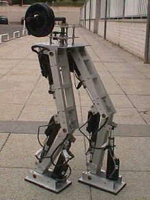
Project on Design of a Biped Robot with Efficient Motion Control

This Project involved construction, design, control and analysis of a Biped Robot. This robot uses the dynamic balancing for the Motion Control. The robot had two legs for walking. The robot was controlled using the 12 FUTABA S3003 servo motors which were controlled in the real time using the serial port programming of Servo motors with the Computer and the Microcontrollers PIC16F84 and PIC16F877.


For Full Project Download: