Low Budget Oscilloscope with Graphical LCD Display:

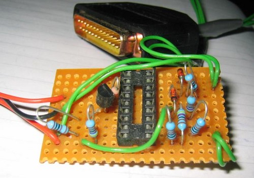
An accurate and simple graphical oscilloscope using a PIC18F2550 microcontroller and an AGM1264F graphical LCD has been constructed using the PIC18F2550 GLCD Text Test as basis. It has the capability of measuring the maximum voltage, peak-to-peak voltage, average voltage, minimum voltage, and the zero-crossing frequency for a DC signal over 100 samples. To capture on rise or fall, the oscilloscope has a built-in edge trigger function that can be set.
Using the change Time Division function, the time scale for the display is variable and can be easily redefined while the voltage range can be changed to 0-5V, 0-2.5V, and 0-1.25V. The relatively slow acquisition time and sampling rate is the main limitations of this oscilloscope due to the fact that the inputs are limited by the constraints of the internal ADC.
A 9V battery is used as the power supply along with a high-accuracy low drop-out linear voltage regulator to provide a stable 5V supply for the microcontroller and the graphical LCD. The power spikes/ripples are prevented by capacitor.


Download File Here:

Thesis on IMPLEMENTING A ROBUST 3-DIMENSIONAL EGOCENTRIC NAVIGATION SYSTEM

Robot Navigation is a large component of current robotics research. In this paper, a method to implement the “go-to-goal” aspect of navigation is discussed. Specifically, I will first discuss a method called Egocentric Navigation, which was developed at Vanderbilt University’s Center for Intelligent Systems. Then improvements toward making the system more accurate and efficient will be proposed. Finally, the experimental and simulation results of this new Egocentric Navigational system follow. In total, this paper will lay out a complete system for implementation on a robot which will accomplish navigation to goal in a landmark-based “egocentric” manner.

For Full Thesis Download:
ROBUST 3-DIMENSIONAL EGOCENTRIC NAVIGATION SYSTEM.Pdf

Using Robotic Hand Technology for the Rehabilitation of Recovering Stroke Patients with Loss of Hand Power

Stroke is the third leading cause of death in the United States. Nearly 700,000 people suffered from stroke last year and two thirds of them survived but were left with any number of disabilities, one such disability is upper extremity paraplegia. If the hand and arm doesn't have therapy immediately after stroke, it will lose it power and muscle control, resulting in a claw like appearance and loss of function. Activities of the patient daily living will be significantly effected. Current therapy on the affected limb in the hospital is expensive and difficult to manage due to the limited amount of resources compared to the number of patients. We introduce a pneumatic actuated wearable hand and forearm device in this thesis. It is designed according to the hand and arm kinematics. It can help the patients keep power on each finger and help maintain the coordination of different fingers to achieve daily living movements. It consists of forearm brace, rehabilitation glove and artificial muscles. The custom made artificial muscles also known as McKinney Artificial Muscles are used in antagonistic pairs to control the fingers flexing and extension. The rehabilitation device is small, lightweight, home-based, and has large force capabilities. It is also affordable to the patients due to the specially designed low-cost artificial muscles. The rehabilitation device was controlled by solenoid valves in conjunction with a Mitsubishi M32/83C 16-bit micro controller. Experiments on the pneumatic elbow brace have shown that it is capable of moving each finger from full extension to flexing, to perform actions like pinching and allows the coordinated movement of two fingers.

For Downloading Full Thesis click below:
Robotic Hand Technology.pdf

Thesis On Space-Time Coding for Large Antenna Arrays

Multiple-input multiple-output (MIMO) systems can greatly improve the capacity and performance of wireless communications. In particular, space-time coding techniques have received much attention in recent years as an efficient approach to achieving the performance gains offered by MIMO channels. Thus far, most work on space-time coding has focused on systems with small antenna arrays or high signal-to-noise ratios (SNRs), for which it has been shown that codes should be designed according to the rank and determinant criteria. For such scenarios, coherent space-time coding and differential space-time modulation (DSTM) schemes have been designed, for systems with or without channel knowledge at the receiver, respectively. In recent years, there has been some work on coherent space-time coding for large arrays, which indicates that the code design metric should be chosen diffently from that for small arrays. In this dissertation, we study the design of space-time coding for large arrays. We focus on three aspects: performance analysis, code construction and decoding algorithms. We first analyze the asymptotic performance of differential space-time modulation. A new upper bound on the pairwise-error probability is derived for large arrays. This bound suggests that Euclidean distance is an appropriate design criterion for DSTM with large numbers of antennas, which is similar to the design of coherent space-time coding for the large-array regime. For two transmit antennas and four or more receive antennas, we use the new design criterion to obtain several new unitary codes with large minimum Euclidean distance. The proposed codes outperform some existing codes, for example, the well-known Alamouti code, for large receive arrays.


Download Full Project Here:
Space-Time Coding for Large Antenna.pdf

Thesis/Project on Vehicle Monitoring and Security System

In this modern, fast moving and insecure world, it is become a basic necessity to be aware of one’s safety. Maximum risks occur in situations wherein an employee travels for money transactions. Also the Company to which he belongs should be aware if there is some problem. What if the person traveling can be tracked and also secured in the case of an emergency?! Fantastic, isn’t it? Of course it is and here’s a system that functions as a tracking and a security system. It’s the VMSS. This system can deal with both pace and security.

The VMSS (Vehicle Monitoring and Security System) is a GPS based vehicle tracking system that is used for security applications as well. The project uses two main underlying concepts. These are GPS (Global Positioning System) and GSM (Global System for Mobile Communication). The main application of this system in this context is tracking the vehicle to which the GPS is connected, giving the information about its position whenever required and for the security of each person travelling by the vehicle. This is done with the help of the GPS satellite and the GPS module attached to the vehicle which needs to be tracked. The GPS antenna present in the GPS module receives the information from the GPS satellite in NMEA (National Marine Electronics Association) format and thus it reveals the position information. This information got from the GPS antenna has to be sent to the Base station wherein it is decoded. For this we use GSM module which has an antenna too. Thus we have at the Base station; the complete data about the vehicle.


Download Full Project:
Vehicle Security System.ace

Project on Automatic Solar Tracking System

AUTOMATIC SOLAR TRACKER starts following the SUN right from dawn, throughout the day, till evening, and starts all over again from dawn next day. On cloudy weathers, it remains still and catches the SUN again as it slips out of clouds. It does all this automatically, employs cheap and inexpensive components, and is very accurate.


For Circuit and Description Download:


Project On Automatic Railway Gate Control & Track Switching

Present project is designed using 8051 microcontroller to avoid railway accidents happening at unattended railway gates, if implemented in spirit. This project utilizes two powerful IR transmitters and two receivers; one pair of transmitter and receiver is fixed at up side (from where the train comes) at a level higher than a
human being in exact alignment and similarly the other pair is fixed at down side of the train direction.


Sensor activation time is so adjusted by calculating the time taken at a certain speed to cross at least one compartment of standard minimum size of the Indian railway. We have considered 5 seconds for this project. Sensors are fixed at 1km on both sides of the gate. We call the sensor along the train direction as ‘foreside sensor’ and the other as ‘aft side sensor’. When foreside receiver gets activated, the gate motor is turned on in one direction and the gate is closed and stays closed until the train crosses the gate and reaches aft side sensors. When aft side receiver gets activated motor turns in opposite direction and gate opens and motor stops. Buzzer will immediately sound at the fore side receiver activation and gate will close after 5 seconds, so giving time to drivers to clear gate area in order to avoid trapping between the gates and stop sound after the train has crossed.

Download the Project here:


Project on Digital thermometer:

This project is a 3-digit digital thermometer easy to build for beginner or hobbyits.PIC16F628 used to read digital value of temperature from a DS1820 sensor.All 7-segments drived by power logic 8-bit shift register TPIC6B595 with open collector output. For the 7-segment need 12V volt to drive because it have 3 LED per one segment.All segment no need to scan display. Source code programming with CCS C Compiler availible.

Downlad The full project from here:

PIC Microcontroller Programmer

In this Post I am given a simple PIC programming Circuit with software which will help you to program the all PIC microcontroller. So this is not a project. If you want to project anything on microcontroller than you must definitely need an programmer. Some PIC programmers are  sold  for $99 in market. But the PicBlaster can be built for under $10 with no boring seminar. Morever it programs FAST and no waiting needs for the EPROM to erase.
Files To Download:
http://www.mediafire.com/?3fmdot4jtnj

Project On Ultrasonic Distance Measurement

This application report describes a distance-measuring system based on ultrasonic sound utilizing the MSP430F413 ultralow-power microcontroller. The system transmits a burst of ultrasonic sound waves towards the subject and then receives the corresponding echo. The MSP430 integrated analog comparator Comparator_A is used to detect the arrival of the echo to the system. The time taken for the ultrasonic burst to travel the distance from the system to the subject and back to the system is accurately measured by the MSP430. Assuming the speed of sound in air at room temperature to be 1100 ft/s, the MSP430 computes the distance between the system and the subject and displays it using a two-digit static LCD driven by its integrated LCD driver. The distance is displayed in inches with an accuracy of ±1 inch. The minimum distance that this system can measure is eight inches and is limited by the transmitter’s transducer settling-time. The maximum distance that can be measured is ninety-nine inches. The amplitude of the echo depends on the reflecting material, shape, and size. Sound-absorbing targets such as carpets and reflecting surfaces less than two square feet in area reflect poorly. The maximum measurable range is lower for such subjects. If the amplitude of the echo received by the system is so low that it is not detectable by the Comparator_A, the system goes out of range. This is indicated by displaying the error message E.


Download Full Project here: 
Ultrasonic Distance Measurement.pdf

Project on LED Bargraph Optical Tachometer


For the electric R/C enthusiast, a tachometer can be a very useful piece of equipment. When I first built this tach back in 1995, it was essential, as there were very few off-the-shelf electric R/C power systems that just worked. At that time, you had to experiment with batteries, speed controls or switches, connectors, and wiring, and a tachometer was a tool to help you measure the results.
Now in 2006, a tachometer is still just as useful. By performing RPM measurements from time to time, problems such as a bad cell in the battery, deteriorating connectors, or damaged motor windings can be detected early before there's a major failure.
There are of course many commercially available tachometers for R/C these days, but if you're like me, it's more fun to build your own. 
 For Details Download here:
Optical Tachometer.pdf


Project On Simple Inexpensive X-Ray Machine

X-ray equipment is costly. Even tubes of relatively low power are priced at $100 and up. Many other commercial X-ray parts are also expensive and difficult to procure. The apparatus supplying high voltage to conventional tubes, while no more complex than the power supply of a husky radio transmitter, calls for special rectifying devices, transformers and other components which are not regularly stocked by dealers in electrical supplies.
Moreover, X-rays have earned a bad reputation as playthings. No distinction can be drawn between the danger of exposure to a high-powered X-ray machine and the fallout of an H-bomb. It is a danger that extends not only to the experimenter but to his potential progeny. Human evolution is the result of mutations caused by, among other agents, cosmic rays and the radiations of radioactive elements in the earth's crust. Any radiation added by man alters the rate of mutation, and is rightly a cause of deep concern.

Simons Project has solved the problem of equipment cost. Protection against exposure to the rays is not difficult to arrange. With these two considerations out of the way, X-rays open a range of experiments equaled by few other phenomena of physics. In addition to providing a source of X-rays for radiographs, a generator of X-rays in combination with accessories enables you to measure the charge of the electron, to study the structure of crystals, to observe the wave-particle duality of matter and radiation, and to probe other microcosmic corners.
 
For Detail download:
Inexpensive X-ray Machine.pdf

Project On Wireless Weather Station

When you check the weather on the television or the radio, it’s always what conditions are like at the airport or some other remote location. But, what are conditions like in my backyard? To address this, I embarked on the design of the Wireless Weather Station. I had meant to do this project many years ago but two bits of technology finally spurred me into action: the first was the development of low-cost, solid state humidity sensors and the second was the availability of small, monolithic RF transceivers.


For Full Project Download here:(Its rar file.you have tto extract it first)
Wireless Weather Station Project.rar

Project/Thesis on Digital Blood Pressure Meter:

Though this is not full Thesis but it definitely  describes a Digital Blood Pressure Meter concept which uses an integrated pressure sensor, analog signal-conditioning circuitry, microcontroller hardware/software and a liquid crystal display. The sensing system reads the cuff pressure (CP) and extracts the pulses for analysis and determination of systolic and diastolic pressure. This design uses a 50 kPa integrated pressure sensor (Freescale Semiconductor, Inc.P/N: MPXV5050GP) yielding a pressure range of 0 mm Hg to 300 mm Hg.


Download The Project from Here:
Digital Blood Pressure Meter.pdf

Project/Thesis on Wireless ECG machine:

The overall objective of this project is to design and implement a prototype ECG system which replaces wired connections between sensor points and a central node with wireless links. Successful implementation of the final system would be of benefit to all involved in the use of electrocardiography as access to, and movement of, the patient would not be impeded by the physical constraints imposed by the cables. Most aspects of the design would also be portable to other sensor applications, making the work relevant to a vast range of systems where movement of sensors is desirable and constrained by hard-wired links. The design and implementation of the wireless link and ECG sensor electronics to produce an ECG signal form the basis of the Wireless ECG Monitors. The Wireless Sensor Protocol (WSP) was hence produced to handle the wireless link. Analogue electronics are used to obtain the signal and to filter noise, while PC based software is used to display the results. The WSP for the ECG system consists of two Slave nodes and one Master node. The Slave node prototype consists of an ECG sensor (with associated electronics), PIC microcontroller and Nordic's nRF401 UHF transceiver, as 'patches' ordinarily placed on the patient. Altera.s Nios Softcore processor (16 bit design) with Nordic's nRF401 UHF transceiver forms the Master (base) node where data is collected and an ECG signal is calculated for displaying to the medical staff.


Download the whole Project from here:

Thesis on A High Performance DSP Based System Architecture for Motor Drive Control


 This paper presents a high speed digital signal processor (DSP) based system architecture for motor drive control. The system achieves fast speed performance by using the 50 MHz TMS320C25 DSP and specialized digital hardware to perform data acquisition and output control tasks usually performed in software. The peripheral hardware has been designed for easy interface to many types of motor drive systems, to make the system generally applicable in the motion control field. The specifications, systematic design, and realization of this general purpose controller are described. Software to support the features of the system is discussed. Experimental results using the proposed system to control a switched reluctance motor drive, both in torque mode and four quadrant speed operation, verify the speed performance of the DSP based system.

For Full Thesis Download:
MOTOR DRIVE CONTROL.Pdf


Thesis on Advanced Single-Stage Power Factor Correction Techniques

Five new single-stage power factor correction (PFC) techniques are developed for single-phase applications. These converters are: Integrated single-stage PFC converters, voltage source charge pump power factor correction (VS-CPPFC) converters, current source CPPFC converters, combined voltage source current source (VSCS) CPPFC converters, and continuous input current (CIC) CPPFC converters.

Integrated single-stage PFC converters are first developed, which combine the PFC converter with a DC/DC converter into a single-stage converter. DC bus voltage stress at light load for the single-stage PFC converters are analyzed. DC bus voltage feedback concept is proposed to reduce the DC bus voltage stress at light load. The principle of operations of proposed converters are presented, implemented and evaluated. The experimental results verify the theoretical analysis.

VS-CPPFC technique use a capacitor in series with a high frequency voltage source to achieve the PFC function. In this way, the input inductor is eliminated. VS-CPPFC AC/DC converters are developed, and their performance is evaluated. VS-CPPFC electronic ballasts with and without dimming function are also presented. The average lamp current control with duty ratio modulation is developed so that the lamp operates in constant power with a low crest factor over the line variation. The experimental results verify the CPPFC concept.

CS-CPPFC technique employs a capacitor in parallel with a high frequency current source to obtain the PFC function. The unity power factor condition and principle of operation are analyzed. By doing so, the switch has less switching current stress, and deals only with the resonant inductor current. Design considerations and experimental results of the CS-CPPFC electronic ballast are presented.

VSCS-CPPFC technique integrates the VS-CPPFC with the CS-CPPFC converters. The circuit derivation, unity power factor condition and design considerations are presented. The developed VSCS-CPPFC converters has constant lamp operation, low crest factor with a high power factor even without any feedback control.

CIC-CPPFC technique is developed by inserting a small inductor in series with the line rectifier for the conceptual VS-CPPFC, CS-CPPFC and VSCS-CPPFC circuits. The circuit derivation and its unity power factor condition are discussed. The input current can be designed to be continuous, and a small line input filter can be used. The circulating current in the resonant tank and the switching current stress are minimized. The average lamp current control with switching frequency modulation is developed, so the developed electronic ballast operates in constant power, low crest factor. The developed CIC-CPPFC electronic ballast has features of low line input current harmonics, constant lamp power, low crest factor, continuous input current, low DC bus voltage stress, small circulating current and switching current stress over a wide range of line input voltage.

For Full Thesis Download:
Power Factor Correction Techniques.pdf

Design and Implementation of computer Interfacing based Thermometer


The Project  is classified into following four sections-
1. Sensing section
2. Measuring section
3. Conditioning or amplification section
4. Interfacing or data acquisition section.
5. Display section.
Sensing and measuring section sense temperature and convert it into electrical quantity as voltage. Conditioning or amplification section amplifies the measuring section output, which is the input of data acquisition section. For conditioning we use non inverting amplifier. At data acquisition section we use analog to digital converter(ADC) for digital output and a multiplexer for converting ADC output from parallel to serial. The multiplexer output is sensed by a parallel port of personal computer by Matlab. Then the digital value is converted to decimal. From temperature versus voltage equation we get measured temperature.

Download The complete project from here:
Temperature measure by PC.pdf

Project on Design of a Biped Robot with Efficient Motion Control

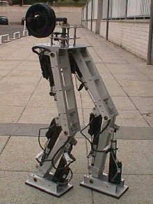
This Project involved construction, design, control and analysis of a Biped Robot. This robot uses the dynamic balancing for the Motion Control. The robot had two legs for walking. The robot was controlled using the 12 FUTABA S3003 servo motors which were controlled in the real time using the serial port programming of Servo motors with the Computer and the Microcontrollers PIC16F84 and PIC16F877.


For Full Project Download: 

Four Fingered Robotic Arm Project

This paper deals with the design, construction, analysis and control of a multi
figured humanoid robotic hand. It uses a very effective mechanism .The
mechanism has a revolute joints to provide different kind o motion to the links The mechanism consists of springs so that the weight of the system is balanced by these springs this reduces the torque required for the motion of the robot .Th mechanism used for the fabrication of the robot are mainly PERSPEX and WOOD because of their light weight.
The robot uses the Japanese futaba servo motors for motion of links. The
robot consists of four servo motors of the rating 6V and torque 3 kg-cm. The
robotic hand can be controlled by both the computer and the micro controller.
The robot is controlled in two ways Manual and Automatic. The robot
picks the object with the help of software program made in Visual Basic .Net.
The control software consists of a GUI (Graphical User Interface) designed in
Visual Basic .Net. The software provides the large flexibility in controlling the
robotic hand.


For Full Project Download:

thesis on Adaptive Power and Rate Control in Third GenerationWideband CDMA Mobile Systems

This thesis proposes novel adaptive power control and rate change schemesand investigates the performance of a Wideband Code Division Multiple Access (W-CDMA)system in conjunction with these adaptive techniques. In these schemes, the transmit power and rate are adapted to the variations of the fading channel using adaptivethresholds based on the probability distribution function (pdf) of the predicted mobilechannel power values.We define a policy similar to the traditional power control technique withthresholds except that the thresholds are set based on several regions of operation in ourAdaptive Transmitter Power Control (TPC) and Adaptive Seamless Rate Change (SRC)schemes. These regions are defined by means of the probability distribution function(pdf) of the total average channel power. The pdf is initially constructed based on thehistory of the predicted channel power values derived from the long-range predictionalgorithm. These regions can be defined such that the system operates at a constant ratioof energy per bit over noise power.In a 1-user model with one channel path, the pdf of the channel power would bean exponential or chi-square function with 2 degrees of freedom. However, in a W-CDMAsystem, normally the rake receiver has several fingers. That is, at the receiver,the system either estimates or predicts the channel coefficients at each rake finger andperforms maximal ratio combining by multiplying each finger with its conjugate or chooses the ones with the highest energy and performs maximal ratio combining on theselected fingers.In a two-user system where the multi-access interference is modeled as theStandard Gaussian Approximation (SGA), the system performance and error probabilityof our W-CDMA system becomes similar to the one for our one-user system.Consequently, in a single user detector system, when all users adopt a similar policy fortheir adaptive power and rate control, the average total Multi-Access Interference (MAI)will be reduced. The resulting channel capacity of the system in this case will beincreased and the system may operate in a lower transmit power level.We evaluate the performance of these schemes using a detailed block diagramsimulation of a W-CDMA system. We model and simulate all major components of thesystem including an accurate model for realistic mobile channels. We present simulationresults to verify that the proposed novel schemes are superior to the traditionalapproaches for transmitter power control and rate change. Furthermore, our simulationresults show that our proposed techniques reduce the effect of Multi Access Interferencein a multi-user system.

Download full thesis From following Link:
Wideband CDMA Mobile Systems.pdf

Thesis on SHORT RANGE UNDERWATER OPTICAL COMMUNICATION LINKS

The future tactical ocean environment will be increasingly complicated. In addition to traditional communication links there will be a proliferation of unmanned vehicles in space, in the air, on the surface, and underwater. To effectively utilize these systems improvements in underwater communication systems are needed. Since radio waves do not propagate in sea water, and acoustic communication systems are relatively low bandwidth the possibility of high speed underwater optical communication systems are considered.

In traditional communication systems, constructing a link budget is often relatively straight forward. In the case of underwater optical systems the variations in the optical properties of ocean water lead to interesting problems when considering the feasibility and reliability of underwater optical links. The main focus of this thesis is to understand how to construct an underwater link budget which includes the effects of scattering and absorption of realistic ocean water.

The secondary focus of the thesis was to construct LED based optical communication systems. This required understanding the behavior of Gallium Nitride LEDs operated under intense electrical pulsing conditions. An optical FM wireless system was constructed for transmitting speech. An LED based Ethernet compatible digital communications system that was capable of operating at 10 Mbps was also constructed and packaged for underwater operation.

For full Thesis Download Here:
UNDERWATER OPTICAL COMMUNICATION.pdf


Holographic Information Systems Thesis:


The goal of this work is to investigate the use of holographic techniques for information processing and transmission systems. Until recently information has been processed and transmitted mainly electronically. With the advent of optical fiber communications the monopoly of electronics has receded in the telecommunications field, but the domain of information processing is still dominated by electronic processors.
This thesis follows a top-down approach to the design of processors that integrate both electronic and optical components. It begins with the design considerations of a compact, rapidly reconfigurable opto-electronic processor, which possesses an optical bus in addition to the traditional electronic bus. The optical bus takes advantage of the massive parallelism that is afforded by optics and can be coupled to a holographic digital memory, allowing rapid reconfiguration of the device. The capability of rapid reconfiguration gives rise to a new computational paradigm, where the reprogramming of the device can become part of the computation. We suggest additional applications of this processor, namely as a smart reading head for large scale holographic disk memories. Finally we present novel algorithms that were developed specifically to take advantage of the additional capabilities of our processor. The next section is concerned with the wavelength and angular tuning of strong volume holograms, both in the reflection and 90-degree geometries. Since photons have no charge, we need to rely on their wave properties to manipulate them, both for long-range transmission, such as telecommunications, and short-range transmission, such as on chip interconnects. In this section we investigate how volumeholograms can be used to selectively redirect information bearing light beams.


The final part of this thesis is concerned with material issues. Holographic recording of strong volume gratings is one of the most commonly used approaches, and photorefractive materials have a strong bearing on the overall performance of the final system.

For Full Thesis Download:
Holographic Information System.pdf


An Impulse Generator Simulation Circuit

This thesis describes the creation of a simulation circuit to match the output of a Marx type Impulse Generator. The goal was to estimate the stray capacitance and insert that capacitance into the simulation circuit to effectively produce an output similar to that of the generator. An actual three-stage impulse generator was used as the base. Several different levels of impulse voltage were tested, and the output waveforms were captured. Research was conducted to formulate the stray capacitance and identify the locations of these capacitances in the generator itself. The simulation circuit was then subjected to several iterations, adjusting the capacitance values to attain an output as close as possible to that of the actual generator.
Conclusions of the research indicate that an effective simulation circuit can be created to give an output that is close to, but not exactly that of, the actual generator. In the research, several areas of error were identified in the actual generator that were not present in the simulation circuit. These areas are discussed in the thesis.

Download The Whole Project here:
http://www.mediafire.com/?2lmmdnmij24


CIRCUIT-LEVEL MODELING OF LASER DIODES

In all semiconductor laser diodes the thermal, electrical, and optical characteristics are integrally related. In this work, a new approach to the modeling of laser diodes that integrates electrical, optical and thermal effects is presented. Also, it is demonstrated how physical device models based on complex differential equations can be easily implemented in the object oriented circuit simulator f REEDATM. Implementations of a Double-Heterojunction Laser Diode (DHLD) and a Vertical Cavity Surface Emitting Laser (VCSEL) diode are described. Simulations and results for both the DHLD and the VCSEL diodes are presented for DC, transient, and Harmonic-Balance analyses.


For Full Thesis Download:
http://www.mediafire.com/?zkfgemjnmyz


TRANSMITTING BIOLOGICAL WAVEFORMS USING A CELLULAR PHONE

There exists a need to remotely monitor fully mobile patients in their natural environments. Monitoring a patient’s biological waveforms can track a patient’s vital signs or facilitate the diagnosis of a disease, which could then be treated to help prolong and/or improve the subject’s life. If a patient must be monitored without the delay associated with delivering data stored on a recording device, biotelemetry is necessary. Biotelemetry entails transmitting biological waveforms to a remote site for recording, processing and analysis. Due to the limitations of the currently popular methods of biotelemetry, this thesis proposes the use of the increasingly prevalent cellular phone system. An adaptor design is developed to facilitate biotelemetry utilizing the most common features of a cell phone, barring the need for cell phone modification, as required for affordability. As cell phones notoriously confound sensitive medical equipment, especially patient-connected devices, their use is often distanced from sensitive equipment. However, the desire to use cell phones to transmit biological waveforms requires their joint-proximity to patient-connected devices.The adaptor must amplify the waveforms while rejecting cell phone interference to achieve an adequate signal-to-noise ratio. As the frequency range of most biological data does not conform to the passband of the phone system, the adapter must modulate the biological data. To limit the adapter’s size and weight, this design exploits the cell phone’s battery power. Methods are also introduced to receive and reconstruct high-fidelity representations of the original biological waveform.


For Detail Download the Following Link:
http://www.mediafire.com/?o4tynkjnnoz

WIRELESS BATTERY CHARGING SYSTEM USING RADIO FREQUENCY ENERGY HARVESTING

It seems these days that everyone has a cellular phone. Whether yours is for business purposes or personal use, you need an efficient way of charging the battery in the phone. But, like most people, you probably don’t like being tethered to the wall. Imagine a system where your cellular phone battery is always charged. No more worrying about forgetting to charge the battery. Sound Impossible?
It is the focus of this thesis to discuss the first step toward realizing this goal. A system will be presented using existing antenna and charge pump technology to charge a cellular phone battery without wires. In this first step, we will use a standard phone, and incorporate the charging technology into a commercially available base station. The base station will contain an antenna tuned to 915MHz and a charge pump. We will discuss the advantages and disadvantages of such a system, and hopefully pave the way for a system incorporated into the phone for charging without the use of a base station.

Through the years, technology has allowed the cellular phone to shrink not only the size of the ICs, but also the batteries. New combinations of materials have made possible the ability to produce batteries that not only are smaller and last longer, but also can be recharged easily. However, as technology has advanced and made our phones smaller and easier to use, we still have one of the original problems: we must plug the phone into the wall in order to recharge the battery. Most people accept this as something that will never change, so they might as well accept it and carry around either extra batteries with them or a charger. Either way, it’s just something extra to weigh a person down. There has been research done in the area of shrinking the charger in order to make it easier to carry with the phone. One study in particular went on to find the lower limit of charger size [1]. But as small as the charger becomes, it still needs to be plugged in to a wall outlet. How can something be called “wireless” when the object in question is required to be plugged in, even though periodically?
Now, think about this; what if it didn’t have to be that way? Most people don’t realize that there is an abundance of energy all around us at all times. We are being bombarded with energy waves every second of the day. Radio and television towers, satellites orbiting earth, and even the cellular phone antennas are constantly transmitting energy. What if there was a way we could harvest the energy that is being transmitted and use it as a source of power? If it could be possible to gather the energy and store it, we could potentially use it to power other circuits. In the case of the cellular phone, this power could be used to recharge a battery that is constantly being depleted. The potential exists for cellular phones, and even more complicated devices - i.e. pocket organizers, person digital assistants (PDAs), and even notebook computers - to become completely wireless.

For Full Report Download below:
Wireless Battery Charger.pdf

A Digital Water Level Meter

Here's an analog water level meter that uses commonly available parts. The output is a voltage that is proportional to the water level.
The monostable is a 555, eg. LM555 or NE555, or could be a ICM7555, the CMOS version of the 555 for lower power consumption. The width of the pulses out of the 555 is proportional to the water level. R7 and C5 form a low pass filter to smooth the DC value of the pulse train. Their values can be increased to lower the cutoff frequency if dynamic response is not required. The lower the cutoff frequency the more noise immunity the device will have.
The zero offset is removed in the differential stage IC1B. The LM324 is a quad op. amp. that can be used in single supply configuration. The maximum output of an LM324 is about 1.5V less than the supply voltage Vcc. The supply can be from a 3-terminal regulator eg LM7808,LM7812, LM7815 - or LM78L08, LM78L12 or LM78L15. The voltage input to one of these regulators needs to be about 2V higher than the regulated voltage. For low power applications a micropower regulator like the MAX666 could be used.


Here Is The Link To Whole Project:

http://www.mediafire.com/?3zeytjiwnyx

Digital Systems & Microprocessors Project

The project will give you the opportunity to use the RTL technique for the design of a system of modest complexity: a reverse polish calculator with 4 significant decimal digits. The project has various milestones among the specifications to allow you to do a top-down design and to tackle the project at various levels of complexity with plenty of scope for individual creativity. A major aspect of the project will be to explore different approaches of developing the different hardware blocks taking special account of meeting spec and synthesis in hardware.


For Whole Project Download here:
http://www.mediafire.com/?zumnunq2nwm

Robotic Arm Project

The main objective of this project is to create the virtual representation of a robot’s working environment. This virtual space gives user the ability to test the physical system without ever having to set up the physical environment and also user can practice without having to be on site. Another benefit of using a virtual space is that we can create any representation needed for the user. To control the robot in the real world, as well as the virtual world, we use MATLAB/Simulink to numerically analyze the inverse dynamics of the system. This allows us to specify the robot’s position that we want and then calculate the joint angles that will move the robot to that desired position. The robot will be used to manipulate a set number of objects with known positions within the system, real world or virtual.


For Detail Download:

http://www.mediafire.com/?cd2iyzhnm3k

Solar Tracking System by Microprocessor:

THEME:

This project uses a stepper motor to control the position of solar energy collectors, using Intel 8085 Microp . The software includes the positioning of collectors through stepper motor & data acquisition and processing in Microprocessor.

OPTICAL SENSING AND PROCESSING :

LDR ( Light Dependent Resistance) is used as a sensor for generating an electric signal proportional to intensity of light falling on it. LDR is mounted at the focus of reflector which is directly mounted on solar energy collectors.

STEPPER MOTOR AND ITS DRIVING CIRCUIT:

The stepper motor requires that its stator windings should be energized in a programmed sequence to cause the motor to run in a given direction and with a required speed.


FOR MORE Please Download:

http://www.mediafire.com/?my2zy2ezyom

Robotic Project:

The Lego Mindstorms NXT has been in the market since 2006 and its potential for robotics application is increasing throughout the years. The Lego Mindstorms NXT educational kit consists of several types of sensors and motors, allowing the robot to be programmed to respond autonomously to different types of situations.

The traditional four-directional analog controller allows motion but is restricted by only the four
direction keys. The Nintendo Wii remote, which is otherwise known as the ‘Wiimote’, expands on the traditional controller by embedding an accelerometer and Infrared (IR) sensors. The accelerometer allows motion capture of the Wiimote along the XYZ axis as well as detecting the roll, yaw and pitch. Combined with the IR sensors, it allows very accurate motion tracking. With the motion tracking capability on top of the traditional controller capabilities, integrating the Wiimote to a robotics kit will allow the robot to be controlled with more finesse.

For Full Project Download here:
http://www.mediafire.com/?jn2nydudn5m

Home Automation System with Mobile Communication and Computer Interfacing

Main Features of the projects:

The Home automation project is divided into two parts:

  1. The electrical appliances with computer parallel port interfacing
  2. The remote external on/off of the whole system

The first part contains a interfacing circuits which should be connected with the PC via a parallel port. The computer should need a high definition language such as C, C+, C++, QuickBasic, visual c, c# etc according to user’s choice. The program will define the address of the LPT port for the computer as well as function and status of the devices whether the devices are on or off.

The second part contains a setup which could turn on/off the whole system externally. Here we use cell phone as it is used widely in modern life. The setup contains a mobile set, a decoder and programmable microcontroller. The decoder will decode the signal from mobile to microcontroller and the microcontroller trigger the relay which is connected to the interfacing unit.

Objective/Task of the project:

The main objective of the project is:

· To generate and develop a circuit that will accept the signals from a computer interface via a port and control the switching of the relays which in turn will control the appliances running on mains power.

· To analyze and develop the instruction codes utilized by the interface to interact with the device using a high-level programming language.

· To design a DTMF decoder circuit which decodes the frequency of the button assigned to mobile phone.

· To connect the decoder with a PIC microcontroller and programming it with necessary condition.

· Finally Implement and combine the whole system.


For Downloading Whole Project :

http://www.mediafire.com/?t43jmdurd3y